ARTICo³ – New Board Templates
Tutorial created on July 10, 2019 by A. Rodríguez
This tutorial covers the following topics:
- Creating a custom reference template for an FPGA board
Requirements
Introduction
ARTICo³ reference designs are located under artico3/templates and can be identified by their names ref_*. These templates provide the basic infrastructure to generate the hardware projects for the multi-accelerator setups.
In this tutorial, you will be creating a new reference design using an already existing one for the Pynq-Z1 board.
More info on ARTICo³ reference designs (i.e., templates) can be found in the documentation.
Create a New Template
Go to the ARTICo³ repository and open a terminal in artico3/templates.
Copy the basic reference design for the Pynq board. You will be using it as starting point.
cp -R ref_linux_pynq_c_basic_vivado_2017.1 ref_linux_pynq_c_custom_vivado_2017.1

Set ARTICo³ Configuration
Open artico3/templates/ref_linux_pynq_c_custom_vivado_2017.1/artico3.cfg and modify it as follows:
--- ref_linux_pynq_c_basic_vivado_2017.1/artico3.cfg    2019-07-09 17:18:28.246390192 +0200
+++ ref_linux_pynq_c_custom_vivado_2017.1/artico3.cfg   2019-07-10 14:56:35.769445810 +0200
@@ -19,7 +19,7 @@
 #                   horizontal (use local buffers per clock region)

 [Shuffler]
-Slots = 4
-PipeDepth = 3
+Slots = 3
+PipeDepth = 0
 ClkBuffer = horizontal
 RstBuffer = global
This file contains the configuration of the ARTICo³ infrastructure, including the number of reconfigurable slots (Slots) and the pipeline depth between static and reconfigurable regions (PipeDepth).
In this tutorial, you will be implementing a reference design with 3 reconfigurable slots and without pipeline logic between static and reconfigurable partitions.
[Optional] Add Custom IP Cores
Copy Source Files
Custom IP cores need to be added in the pcores folder within the reference design.
In this tutorial, you will be adding one of the dummy cores available in artico3/lib/pcores directory. To do so, execute the following in the template folder:
ln -s ../../../lib/pcores/test_axi4full_v1_00_a pcores/test_axi4full_v1_00_a

Modify IP Library Generation Script
Open artico3/templates/ref_linux_pynq_c_custom_vivado_2017.1/create_ip_library.tcl and modify it as follows:
--- ref_linux_pynq_c_basic_vivado_2017.1/create_ip_library.tcl  2019-07-09 17:18:28.246390192 +0200
+++ ref_linux_pynq_c_custom_vivado_2017.1/create_ip_library.tcl 2019-07-10 15:19:36.105358183 +0200
@@ -299,6 +299,7 @@
 load_artico3_interfaces $ip_repo

 import_pcore $ip_repo artico3_shuffler_v1_00_a ""
+import_pcore $ip_repo test_axi4full_v1_00_a ""

 # Import all required ARTICo3 kernels
 <a3<generate for KERNELS>a3>
This file contains the script that creates a custom IP repository from all the source codes available in the subfolder pcores inside the template.
Modify Vivado Project Generation Script
Open artico3/templates/ref_linux_pynq_c_custom_vivado_2017.1/export.tcl and modify it as follows:
--- ref_linux_pynq_c_basic_vivado_2017.1/export.tcl  2019-07-09 17:18:28.246390192 +0200
+++ ref_linux_pynq_c_custom_vivado_2017.1/export.tcl 2019-07-10 16:22:30.713118567 +0200
@@ -184,14 +184,19 @@
     create_bd_cell -type ip -vlnv cei.upm.es:artico3:<a3<SlotCoreName>a3>:[string range <a3<SlotCoreVersion>a3> 0 2] "a3_slot_<a3<id>a3>"
 <a3<end generate>a3>

+    # Create other instances
+    create_bd_cell -type ip -vlnv cei.upm.es:artico3:test_axi4full:1.0 test_axi4full_0
+    set_property -dict [list CONFIG.C_MEMORY_SIZE {65536}] [get_bd_cells test_axi4full_0]
+
     # Required to avoid problems with AXI Interconnect
     set_property -dict [list CONFIG.C_S_AXI_ID_WIDTH {12}] [get_bd_cells artico3_shuffler_0]
+    set_property -dict [list CONFIG.C_S_AXI_ID_WIDTH {12}] [get_bd_cells test_axi4full_0]

     # Create and configure new AXI Interconnects
     create_bd_cell -type ip -vlnv xilinx.com:ip:axi_interconnect:2.1 axi_a3ctrl
     set_property -dict [ list CONFIG.NUM_MI {1} CONFIG.NUM_SI {1}] [get_bd_cells axi_a3ctrl]
     create_bd_cell -type ip -vlnv xilinx.com:ip:axi_interconnect:2.1 axi_a3data
-    set_property -dict [ list CONFIG.NUM_MI {1} CONFIG.NUM_SI {1}] [get_bd_cells axi_a3data]
+    set_property -dict [ list CONFIG.NUM_MI {2} CONFIG.NUM_SI {1}] [get_bd_cells axi_a3data]

     # Connect AXI interfaces
     connect_bd_intf_net -intf_net axi_a3ctrl_S00_AXI [get_bd_intf_pins axi_a3ctrl/S00_AXI] [get_bd_intf_pins processing_system7_0/M_AXI_GP0]
@@ -199,6 +204,7 @@

     connect_bd_intf_net -intf_net axi_a3data_S00_AXI [get_bd_intf_pins axi_a3data/S00_AXI] [get_bd_intf_pins processing_system7_0/M_AXI_GP1]
     connect_bd_intf_net -intf_net axi_a3data_M00_AXI [get_bd_intf_pins axi_a3data/M00_AXI] [get_bd_intf_pins artico3_shuffler_0/s01_axi]
+    connect_bd_intf_net -intf_net axi_a3data_M01_AXI [get_bd_intf_pins axi_a3data/M01_AXI] [get_bd_intf_pins test_axi4full_0/S_AXI]

     # Connect clocks
     connect_bd_net [get_bd_pins processing_system7_0/FCLK_CLK0] \
@@ -210,8 +216,10 @@
                         [get_bd_pins processing_system7_0/M_AXI_GP1_ACLK] \
                         [get_bd_pins axi_a3data/ACLK] \
                         [get_bd_pins axi_a3data/M00_ACLK] \
+                        [get_bd_pins axi_a3data/M01_ACLK] \
                         [get_bd_pins axi_a3data/S00_ACLK] \
-                        [get_bd_pins artico3_shuffler_0/s_axi_aclk]
+                        [get_bd_pins artico3_shuffler_0/s_axi_aclk] \
+                        [get_bd_pins test_axi4full_0/S_AXI_ACLK]

     # Connect resets
     connect_bd_net [get_bd_pins reset_0/ext_reset_in] [get_bd_pins processing_system7_0/FCLK_RESET0_N]
@@ -222,10 +230,12 @@
                         [get_bd_pins axi_a3ctrl/S00_ARESETN] \
                         [get_bd_pins axi_a3data/ARESETN] \
                         [get_bd_pins axi_a3data/M00_ARESETN] \
+                        [get_bd_pins axi_a3data/M01_ARESETN] \
                         [get_bd_pins axi_a3data/S00_ARESETN]

     connect_bd_net [get_bd_pins reset_0/peripheral_aresetn] \
-                        [get_bd_pins artico3_shuffler_0/s_axi_aresetn]
+                        [get_bd_pins artico3_shuffler_0/s_axi_aresetn] \
+                        [get_bd_pins test_axi4full_0/S_AXI_ARESETN]

     # Connect interrupts
     create_bd_cell -type ip -vlnv xilinx.com:ip:xlconcat:2.1 xlconcat_0
@@ -242,6 +252,7 @@
     # Generate memory-mapped segments for custom peripherals
     create_bd_addr_seg -range 1M -offset 0x7aa00000 [get_bd_addr_spaces processing_system7_0/Data] [get_bd_addr_segs {artico3_shuffler_0/s00_axi/reg0}] SEG0
     create_bd_addr_seg -range 1M -offset 0x8aa00000 [get_bd_addr_spaces processing_system7_0/Data] [get_bd_addr_segs {artico3_shuffler_0/s01_axi/reg0}] SEG1
+    create_bd_addr_seg -range 64K -offset 0x8ab00000 [get_bd_addr_spaces processing_system7_0/Data] [get_bd_addr_segs {test_axi4full_0/S_AXI/reg0}] SEG2

 # END
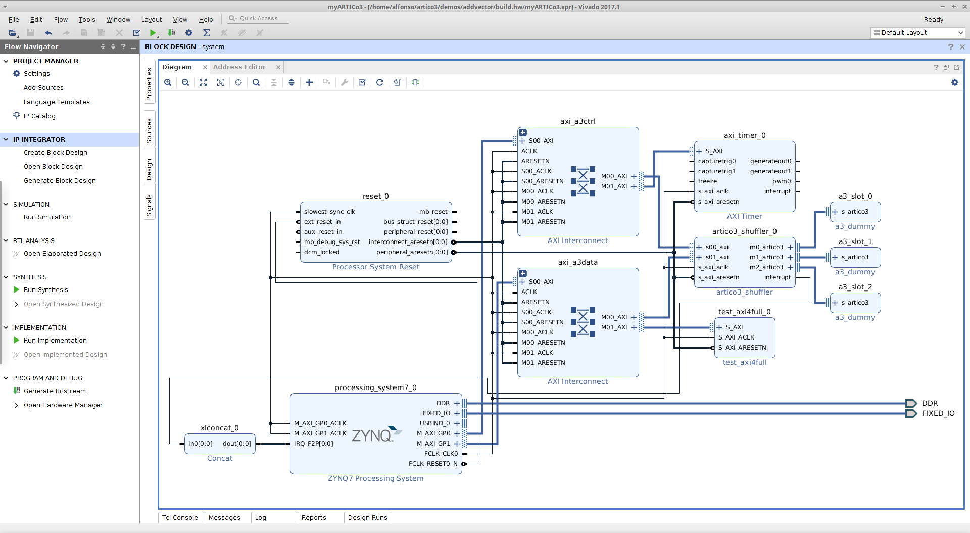
Each of the modified sections in the previous code has a specific purpose:
- First section: instantiate custom IP and configure it
- Second section: connect AXI interfaces
- Third section: connect clocks
- Fourth section: connect resets
- Fifth section: configure memory maps
[Optional] Add Xilinx IP Cores
Modify Vivado Project Generation Script
Open artico3/templates/ref_linux_pynq_c_custom_vivado_2017.1/export.tcl and modify it as follows:
--- ref_linux_pynq_c_custom_vivado_2017.1/export_custom.tcl 2019-07-10 16:22:30.713118567 +0200
+++ ref_linux_pynq_c_custom_vivado_2017.1/export.tcl 2019-07-10 16:21:56.609120732 +0200
@@ -187,6 +187,7 @@
     # Create other instances
     create_bd_cell -type ip -vlnv cei.upm.es:artico3:test_axi4full:1.0 test_axi4full_0
     set_property -dict [list CONFIG.C_MEMORY_SIZE {65536}] [get_bd_cells test_axi4full_0]
+    create_bd_cell -type ip -vlnv xilinx.com:ip:axi_timer:2.0 axi_timer_0

     # Required to avoid problems with AXI Interconnect
     set_property -dict [list CONFIG.C_S_AXI_ID_WIDTH {12}] [get_bd_cells artico3_shuffler_0]
@@ -194,13 +195,14 @@

     # Create and configure new AXI Interconnects
     create_bd_cell -type ip -vlnv xilinx.com:ip:axi_interconnect:2.1 axi_a3ctrl
-    set_property -dict [ list CONFIG.NUM_MI {1} CONFIG.NUM_SI {1}] [get_bd_cells axi_a3ctrl]
+    set_property -dict [ list CONFIG.NUM_MI {2} CONFIG.NUM_SI {1}] [get_bd_cells axi_a3ctrl]
     create_bd_cell -type ip -vlnv xilinx.com:ip:axi_interconnect:2.1 axi_a3data
     set_property -dict [ list CONFIG.NUM_MI {2} CONFIG.NUM_SI {1}] [get_bd_cells axi_a3data]

     # Connect AXI interfaces
     connect_bd_intf_net -intf_net axi_a3ctrl_S00_AXI [get_bd_intf_pins axi_a3ctrl/S00_AXI] [get_bd_intf_pins processing_system7_0/M_AXI_GP0]
     connect_bd_intf_net -intf_net axi_a3ctrl_M00_AXI [get_bd_intf_pins axi_a3ctrl/M00_AXI] [get_bd_intf_pins artico3_shuffler_0/s00_axi]
+    connect_bd_intf_net -intf_net axi_a3ctrl_M01_AXI [get_bd_intf_pins axi_a3ctrl/M01_AXI] [get_bd_intf_pins axi_timer_0/S_AXI]

     connect_bd_intf_net -intf_net axi_a3data_S00_AXI [get_bd_intf_pins axi_a3data/S00_AXI] [get_bd_intf_pins processing_system7_0/M_AXI_GP1]
     connect_bd_intf_net -intf_net axi_a3data_M00_AXI [get_bd_intf_pins axi_a3data/M00_AXI] [get_bd_intf_pins artico3_shuffler_0/s01_axi]
@@ -212,6 +214,7 @@
                         [get_bd_pins processing_system7_0/M_AXI_GP0_ACLK] \
                         [get_bd_pins axi_a3ctrl/ACLK] \
                         [get_bd_pins axi_a3ctrl/M00_ACLK] \
+                        [get_bd_pins axi_a3ctrl/M01_ACLK] \
                         [get_bd_pins axi_a3ctrl/S00_ACLK] \
                         [get_bd_pins processing_system7_0/M_AXI_GP1_ACLK] \
                         [get_bd_pins axi_a3data/ACLK] \
@@ -219,7 +222,8 @@
                         [get_bd_pins axi_a3data/M01_ACLK] \
                         [get_bd_pins axi_a3data/S00_ACLK] \
                         [get_bd_pins artico3_shuffler_0/s_axi_aclk] \
-                        [get_bd_pins test_axi4full_0/S_AXI_ACLK]
+                        [get_bd_pins test_axi4full_0/S_AXI_ACLK] \
+                        [get_bd_pins axi_timer_0/s_axi_aclk]

     # Connect resets
     connect_bd_net [get_bd_pins reset_0/ext_reset_in] [get_bd_pins processing_system7_0/FCLK_RESET0_N]
@@ -227,6 +231,7 @@
     connect_bd_net [get_bd_pins reset_0/Interconnect_aresetn] \
                         [get_bd_pins axi_a3ctrl/ARESETN] \
                         [get_bd_pins axi_a3ctrl/M00_ARESETN] \
+                        [get_bd_pins axi_a3ctrl/M01_ARESETN] \
                         [get_bd_pins axi_a3ctrl/S00_ARESETN] \
                         [get_bd_pins axi_a3data/ARESETN] \
                         [get_bd_pins axi_a3data/M00_ARESETN] \
@@ -235,6 +240,7 @@

     connect_bd_net [get_bd_pins reset_0/peripheral_aresetn] \
                         [get_bd_pins artico3_shuffler_0/s_axi_aresetn] \
+                        [get_bd_pins axi_timer_0/s_axi_aresetn] \
                         [get_bd_pins test_axi4full_0/S_AXI_ARESETN]

     # Connect interrupts
@@ -253,6 +259,7 @@
     create_bd_addr_seg -range 1M -offset 0x7aa00000 [get_bd_addr_spaces processing_system7_0/Data] [get_bd_addr_segs {artico3_shuffler_0/s00_axi/reg0}] SEG0
     create_bd_addr_seg -range 1M -offset 0x8aa00000 [get_bd_addr_spaces processing_system7_0/Data] [get_bd_addr_segs {artico3_shuffler_0/s01_axi/reg0}] SEG1
     create_bd_addr_seg -range 64K -offset 0x8ab00000 [get_bd_addr_spaces processing_system7_0/Data] [get_bd_addr_segs {test_axi4full_0/S_AXI/reg0}] SEG2
+    create_bd_addr_seg -range 64K -offset 0x42800000 [get_bd_addr_spaces processing_system7_0/Data] [get_bd_addr_segs {axi_timer_0/S_AXI/Reg}] SEG3

 # END
![]() IMPORTANT: this section assumes incremental development. Hence, the custom IP modifications are also included in the
IMPORTANT: this section assumes incremental development. Hence, the custom IP modifications are also included in the .diff file.
Modify FPGA Floorplan
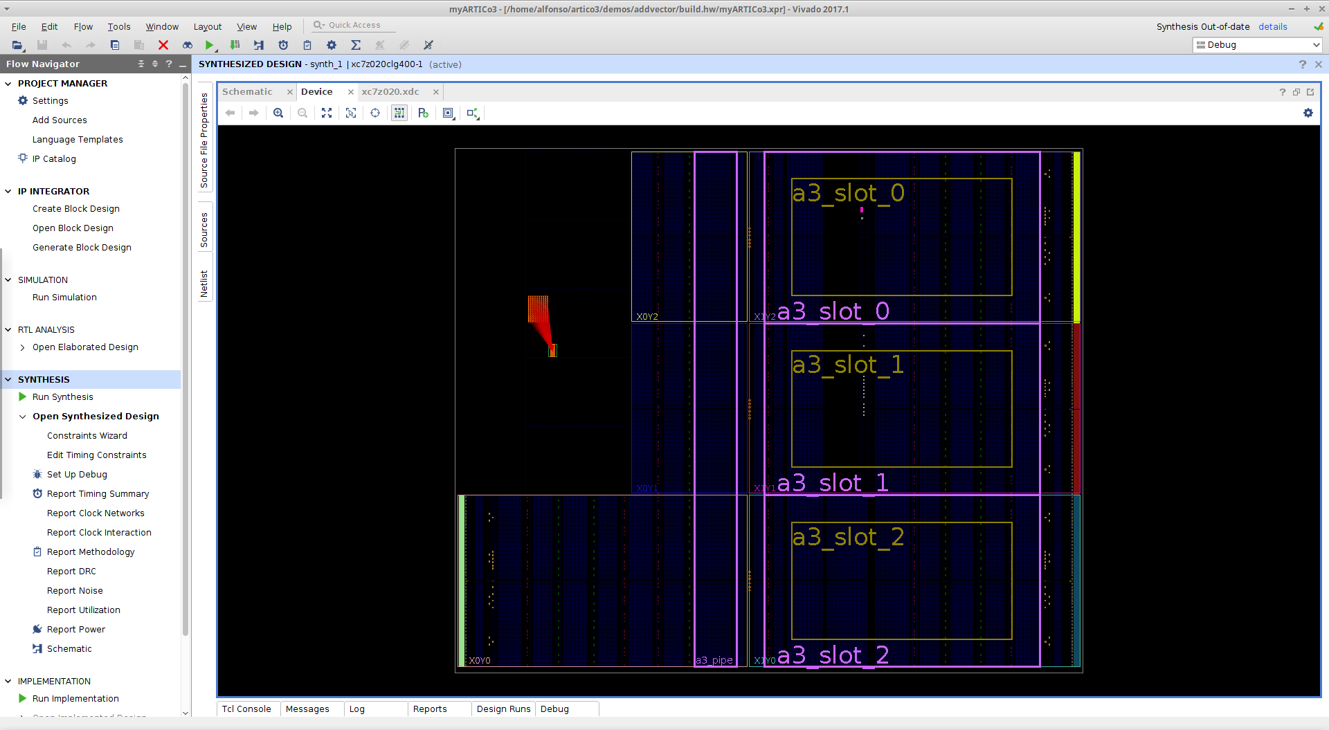
Open artico3/templates/ref_linux_pynq_c_custom_vivado_2017.1/xc7z020.xdc and modify it as follows:
--- ref_linux_pynq_c_basic_vivado_2017.1/xc7z020.xdc    2019-07-09 17:18:28.246390192 +0200
+++ ref_linux_pynq_c_custom_vivado_2017.1/xc7z020.xdc   2019-07-10 16:47:06.245024898 +0200
@@ -1,52 +1,39 @@
 # Configure pipeline logic
 create_pblock a3_pipe
 add_cells_to_pblock [get_pblocks a3_pipe] [get_cells -quiet -hierarchical pipe_logic*]
-resize_pblock [get_pblocks a3_pipe] -add {SLICE_X44Y0:SLICE_X53Y149}
-resize_pblock [get_pblocks a3_pipe] -add {RAMB18_X3Y0:RAMB18_X3Y59}
-resize_pblock [get_pblocks a3_pipe] -add {RAMB36_X3Y0:RAMB36_X3Y29}
+resize_pblock [get_pblocks a3_pipe] -add {SLICE_X36Y0:SLICE_X49Y149}

 # Set IP cores as reconfigurable partitions
 set_property HD.RECONFIGURABLE true [get_cells -quiet -hierarchical a3_slot_0]
 set_property HD.RECONFIGURABLE true [get_cells -quiet -hierarchical a3_slot_1]
 set_property HD.RECONFIGURABLE true [get_cells -quiet -hierarchical a3_slot_2]
-set_property HD.RECONFIGURABLE true [get_cells -quiet -hierarchical a3_slot_3]

 # Configure slot #0
 create_pblock a3_slot_0
 add_cells_to_pblock [get_pblocks a3_slot_0] [get_cells -quiet -hierarchical a3_slot_0]
-resize_pblock [get_pblocks a3_slot_0] -add {SLICE_X80Y100:SLICE_X113Y149}
+resize_pblock [get_pblocks a3_slot_0] -add {SLICE_X52Y100:SLICE_X113Y149}
 resize_pblock [get_pblocks a3_slot_0] -add {DSP48_X3Y40:DSP48_X4Y59}
-resize_pblock [get_pblocks a3_slot_0] -add {RAMB18_X4Y40:RAMB18_X5Y59}
-resize_pblock [get_pblocks a3_slot_0] -add {RAMB36_X4Y20:RAMB36_X5Y29}
+resize_pblock [get_pblocks a3_slot_0] -add {RAMB18_X3Y40:RAMB18_X5Y59}
+resize_pblock [get_pblocks a3_slot_0] -add {RAMB36_X3Y20:RAMB36_X5Y29}
 set_property RESET_AFTER_RECONFIG true [get_pblocks a3_slot_0]
 set_property SNAPPING_MODE ON [get_pblocks a3_slot_0]

 # Configure slot #1
 create_pblock a3_slot_1
 add_cells_to_pblock [get_pblocks a3_slot_1] [get_cells -quiet -hierarchical a3_slot_1]
-resize_pblock [get_pblocks a3_slot_1] -add {SLICE_X80Y50:SLICE_X113Y99}
+resize_pblock [get_pblocks a3_slot_1] -add {SLICE_X52Y50:SLICE_X113Y99}
 resize_pblock [get_pblocks a3_slot_1] -add {DSP48_X3Y20:DSP48_X4Y39}
-resize_pblock [get_pblocks a3_slot_1] -add {RAMB18_X4Y20:RAMB18_X5Y39}
-resize_pblock [get_pblocks a3_slot_1] -add {RAMB36_X4Y10:RAMB36_X5Y19}
+resize_pblock [get_pblocks a3_slot_1] -add {RAMB18_X3Y20:RAMB18_X5Y39}
+resize_pblock [get_pblocks a3_slot_1] -add {RAMB36_X3Y10:RAMB36_X5Y19}
 set_property RESET_AFTER_RECONFIG true [get_pblocks a3_slot_1]
 set_property SNAPPING_MODE ON [get_pblocks a3_slot_1]

 # Configure slot #2
 create_pblock a3_slot_2
 add_cells_to_pblock [get_pblocks a3_slot_2] [get_cells -quiet -hierarchical a3_slot_2]
-resize_pblock [get_pblocks a3_slot_2] -add {SLICE_X80Y0:SLICE_X113Y49}
+resize_pblock [get_pblocks a3_slot_2] -add {SLICE_X52Y0:SLICE_X113Y49}
 resize_pblock [get_pblocks a3_slot_2] -add {DSP48_X3Y0:DSP48_X4Y19}
-resize_pblock [get_pblocks a3_slot_2] -add {RAMB18_X4Y0:RAMB18_X5Y19}
-resize_pblock [get_pblocks a3_slot_2] -add {RAMB36_X4Y0:RAMB36_X5Y9}
+resize_pblock [get_pblocks a3_slot_2] -add {RAMB18_X3Y0:RAMB18_X5Y19}
+resize_pblock [get_pblocks a3_slot_2] -add {RAMB36_X3Y0:RAMB36_X5Y9}
 set_property RESET_AFTER_RECONFIG true [get_pblocks a3_slot_2]
 set_property SNAPPING_MODE ON [get_pblocks a3_slot_2]
-
-# Configure slot #3
-create_pblock a3_slot_3
-add_cells_to_pblock [get_pblocks a3_slot_3] [get_cells -quiet -hierarchical a3_slot_3]
-resize_pblock [get_pblocks a3_slot_3] -add {SLICE_X0Y0:SLICE_X31Y49}
-resize_pblock [get_pblocks a3_slot_3] -add {DSP48_X0Y0:DSP48_X1Y19}
-resize_pblock [get_pblocks a3_slot_3] -add {RAMB18_X0Y0:RAMB18_X1Y19}
-resize_pblock [get_pblocks a3_slot_3] -add {RAMB36_X0Y0:RAMB36_X1Y9}
-set_property RESET_AFTER_RECONFIG true [get_pblocks a3_slot_3]
-set_property SNAPPING_MODE ON [get_pblocks a3_slot_3]
This will remove one reconfigurable slot and reshape the other three.
[Info] Floorplan Tuning
![]() IMPORTANT: this section assumes you have not performed the previous one.
IMPORTANT: this section assumes you have not performed the previous one.
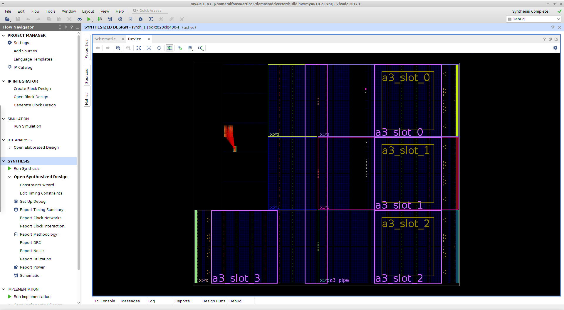
If you want to fine-tune the floorplanning of your template, you can do so using Vivado.
First, use any ARTICo³ demo, configuring it to use the custom template (see here). Use the ARTICo³ toolchain to create the hardware project using export_hw. Then, open the generated project using Vivado:
source /opt/Xilinx/Vivado/2017.1/settings64.sh
vivado <path_to_artico3_repo>/demos/addvector/build.hw/myARTICo3.xpr

Synthesize the project, and open the device view in the synthesis checkpoint.

Edit the floorplan until it fits your requirements.

Save the constraints in Vivado, and copy the .xdc file (<path_to_artico3_repo>/demos/addvector/build.hw/xc7z020.xdc) to the template folder (<path_to_artico3_repo>/templates/ref_linux_pynq_c_custom_vivado_2017.1).
Test the New Template
Go to any of the ARTICo³ demos, and modify the build.cfg file to use the new template:
--- a/demos/addvector/build.cfg
+++ b/demos/addvector/build.cfg
@@ -25,7 +25,7 @@
 Name = AddVector
 TargetBoard = pynq,c
 TargetPart = xc7z020clg400-1
-ReferenceDesign = basic
+ReferenceDesign = custom
 TargetOS = linux
 TargetXil = vivado,2017.1
![]() IMPORTANT: all ARTICo³ demos are configured to use the
IMPORTANT: all ARTICo³ demos are configured to use the basic template, which has 4 reconfigurable slots. Make sure to also modify the application code to avoid run-time errors.
--- a/demos/addvector/src/application/main.c
+++ b/demos/addvector/src/application/main.c
@@ -57,19 +57,17 @@ int main(int argc, char *argv[]) {

     // Load accelerators
     gettimeofday(&t0, NULL);
-    artico3_load("addvector", 0, 0, 0, 1);
+    artico3_load("addvector", 0, 1, 0, 1);
     artico3_load("addvector", 1, 1, 0, 1);
     artico3_load("addvector", 2, 1, 0, 1);
-    artico3_load("addvector", 3, 1, 0, 1);
     gettimeofday(&tf, NULL);
     t_hw = ((tf.tv_sec - t0.tv_sec) * 1000.0) + ((tf.tv_usec - t0.tv_usec) / 1000.0);
     printf("Kernel loading : %.6f ms\n", t_hw);

     gettimeofday(&t0, NULL);
-    artico3_load("addvector", 0, 0, 0, 0);
+    artico3_load("addvector", 0, 1, 0, 0);
     artico3_load("addvector", 1, 1, 0, 0);
     artico3_load("addvector", 2, 1, 0, 0);
-    artico3_load("addvector", 3, 1, 0, 0);
     gettimeofday(&tf, NULL);
     t_hw = ((tf.tv_sec - t0.tv_sec) * 1000.0) + ((tf.tv_usec - t0.tv_usec) / 1000.0);
     printf("Kernel loading (no force): %.6f ms\n", t_hw);
Use the ARTICo³ toolchain to build the project and generate both FPGA bitstreams (export_hw and build_hw) and application executable (export_sw and build_sw). Copy required files to target platform and run the application.
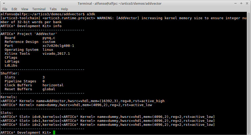
![]() IMPORTANT: you can use the
IMPORTANT: you can use the info command in the ARTICo³ toolchain to verify that everything is as expected.

The solution of this tutorial can be downloaded from here. It contains the custom reference design that should be extracted in the templates folder of the ARTICo³ repository.