Fine-grain reconfiguration tutorial
This tutorial shows how to build a reconfigurable system that mixes medium-grain and fine-grain reconfiguration. In this tutorial we are going to modify the static system created in the first tutorial to add the fine-grain reconfiguration engine. The reconfigurable partition of the static system will allocate two modules with fine-grain reconfigurable elements as shown in the image below.

Requirements
- Medium-grain tutorial
- Basic knowledge of Vivado and Xilinx SDK
- The tutorial is implemented in a xc7z020clg400-1 SoC. This tutorial can be followed almost entirely without having the device. The only limitation is that the user cannot test if the system is working correctly.
Static system project
Create a new project (in any path) and introduce the following commands in the Tcl console to generate the static system block design:
import_files -norecurse <path to IMPRESS>/examples/sources/fine/design_time/static/reconf_part.vhd
source <path to IMPRESS>/examples/sources/fine/design_time/static/static_fine.tcl
Then, generate the wrapper of the block design (right-click in the block design file -> Create HDL wrapper) and ensure that it is marked as the top source. Click the Run Synthesis button and wait until the synthesis step finishes. Open the synthesized design and write a design checkpoint inside the folder <path to IMPRESS>/examples/sources/fine/design_time/static/synth_checkpoint/static_system.dcp
Implementing the reconfigurable system with IMPRESS
The input files to build the reconfigurable system are located in <path to IMPRESS>/examples/fine_grain/. To implement the reconfigurable system open Vivado and introduce the following commands:
source <path to IMPRESS>/design_time/reconfiguration_tool/impress.tcl
implement_reconfigurable_design <path to IMPRESS>/examples/fine_grain/project_info
This generates a folder called IMPRESS_build that contains synthesis & implementation checkpoints and the static and partial bitstreams.
The top module includes five fine-grain components (two constants, two multiplexers and one functional unit). If we open the checkpoint <path to IMPRESS>/examples/fine_grain/impress_build/IMPLEMENTED/group1_top_module.dcp we can see that there are three columns reserved to fine-grain components. The first one is for constants, the second one for multiplexers and the third one for functional units. If we inspect the first column we can see that the first LUTs are part of the constant with position value 1, The following LUTs are part of the constant with position value 2 and finally the rest of the column is filled with dummy LUTs.
Run-time management
Now we are going to design the software program in charge of downloading the partial bitstreams. First, open the Vivado project where we built the static system sources in the first section of this tutorial. In order to build the software it is necessary to export the hardware. To do so click File->Export->Export Hardware->Ok without marking the include bitstream option. Now click in File->Launch SDK.
Once in the SDK, create a new project by clicking File->New->Application Project. Name the project fine, click next and select Empty application.
We have to modify the system.mss in the BSP to include the generic fat file system library which allows using SD memory cards. Open the system.mss file and click Modify this BSP’s Settings and select xilffs. In the xilffs tab change use_lfn to true to allow long names.
Now we have to import IMPRESS run_time source files to the SDK project. Import the files xc7z020 (.c and .h) and series7.h from <path to IMPRESS>/run_time/FPGA_templates and files IMPRESS_reconfiguration (.c and .h) and reconfig_pcap (.c and .h) from *
IMPRESS_reconfiguration_parameters.h
In fine-grain reconfigurable systems we have to fill the following parameters:
- MAX_CONSTANTS: represents the maximum number of constants that one element can have. In this case the maximum number of constant an element can have is two (the top and bottom module have two constants)
- MAX_MUXES: represents the maximum number of multiplexers that one element can have. In this case the maximum number of muxes an element can have is two (the top module has two muxes)
- MAX_FU: represents the maximum number of FUs that one element can have. In this case the maximum number of FU an element can have is one (the top and bottom module have one FU)
- MAX_BITS_PER_CONSTANT: represents the maximum number of bits a constant can have. In this case the maximum number of bits a constant can have is eight (the top and bottom module have constants with eight bits)
- MAX_COLUMNS_CONSTANTS: represents the maximum number of columns that are reserved for constants in an element. In this case is one as constants only occupy one column in both modules.
- MAX_COLUMNS_MUX: represents the maximum number of columns that are reserved for multiplexers in an element. In this case is one as muxes only occupy one column in the top module.
- MAX_COLUMNS_FU: represents the maximum number of columns that are reserved for functional units in an element. In this case is one as FUs only occupy one column in the bottom modules.
- MAX_COLUMN_OFFSETS: represents the maximum number of different column offsets in an element. In this case this parameter is set to one as all the fine-grain components have the same offset value
IMPRESS_reconfiguration_parameters.c
This file contains the elements variable that stores the information of each reconfigurable module. In reconfigurable modules that contain fine-grain components it is necessary to include fine-grain fields that represent the number and location of these components. For example in the top module we have the following fields related to fine-grain constants:
- num_constants: number of constants in the component in this case two.
- constant_column_offset: array with the offset of each constant starting from the constant with the lower position parameter. In this case the offset value of both constants is zero.
- num_bits_in_constant: array with the number of bits of each constant starting from the constant with the lower position parameter. In this case the number of bits of both constants is eight.
- num_constant_columns: array with the number of columns that occupy the constants with the same offset. In this case because both constants have the same offset value this parameter must be the same. In this example the num_constant_columns value of both constants is zero which means that IMPRESS uses the minimum number of columns needed to place all the LUT constants.
lscript.ld In this file it is necessary to reduce the amount of memory RAM that the program can use so that ps7_ddr_0 base address + size equals INITIAL_ADDR_RAM. Doing this we ensure that memory RAM from INITIAL_ADDR_RAM address is free to use to store partial bitstreams.
main.c
The main.c contains the steps needed to reconfigure modules in the static system. These are the important steps that are needed to reconfigure a system:
- Declare a virtual_architecture_t variable.
- Call init_virtual_architecture()
- Map each element of the virtual architecture variable to a region of the FPGA using change_partition_position function
- Start reconfiguring modules using change_partition_element function.
- Start changing fine-grain components using the functions change_partition_constant, change_partition_mux and change_partition_FU. These functions only changes the fine-grain components locally but it does not update the FPGA
- The function reconfigure_fine_grain reconfigures the FPGA with the new values changed in the previous step.
Testing the system
Once the source files have been imported into the project we can test the system in the FPGA.
First connect the board (e.g., PYNQ or Zedboard) to the computer. Insert in the board an SD memory card with the partial bitstreams stored in <path to IMPRESS>/examples/fine_grain/impress_build/BITSTREAMS/. Right-click in the project and select debug as->debug configurations select the last option (system debugger). In the bitstream field select browse and select the static bitstream stored in <path to IMPRESS>/examples/fine_grain/impress_build/BITSTREAMS/static.bit. Check reset entire system and press Debug.
Press run. Now go to to the static system project and select Open Target -> Auto Connect in the flow navigator ribbon.
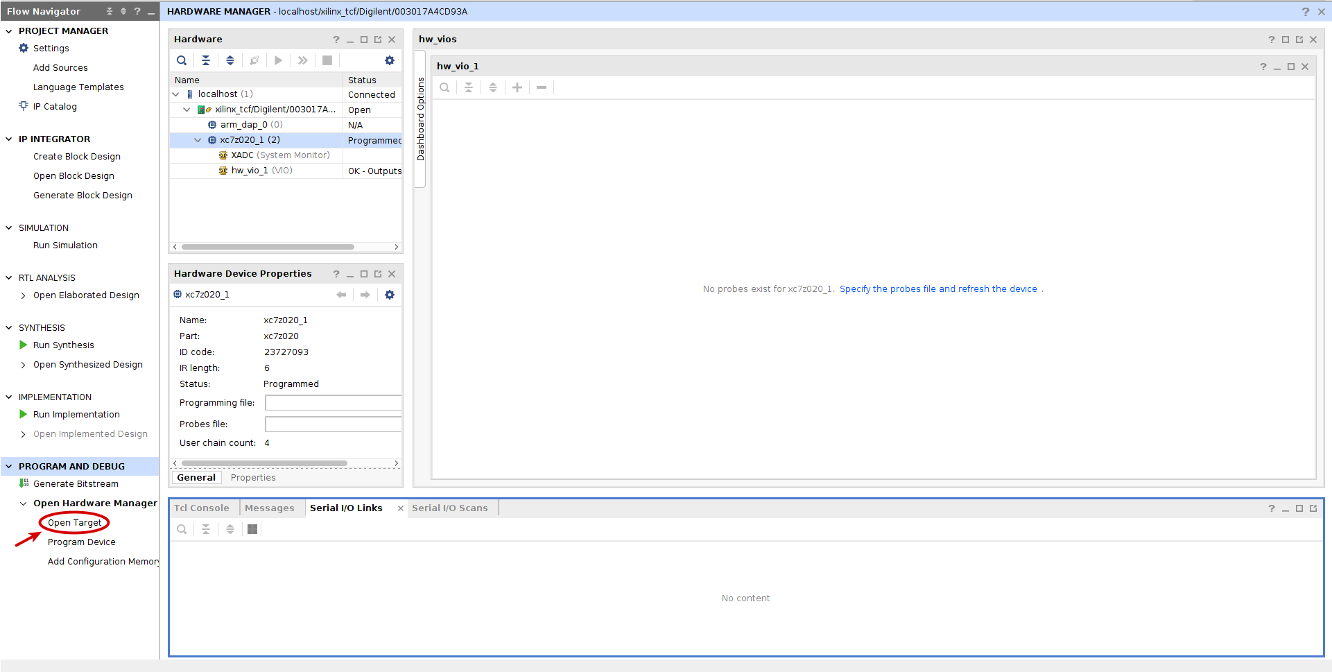
Click the Specify the probes (.ltx) file and refresh the device. button and select the probes generated under the static bitstream folder at <path to IMPRESS>/examples/fine_grain/impress_build/BITSTREAMS/static_probes.ltx
static_probes.ltx*. Add all the probes and give different values to probes vio_0_probe_out0 and vio_0_probe_out1. vio_0_probe_out2 is the reset signal of the reconfigurable module and its value should be 0. Check that the value of probe reconf_part_0_output1[7:0] is (probe_out_1 + 5 (first constant in top module)) & 0x83 (constant in bottom module)
NOTE: in this tutorial it is not necessary to reset the module to ensure that the module works correctly but this may be the case in more complex reconfigurable modules